Getting Started Developing for the LILYGO T-Deck
02 Mar 2025Introduction
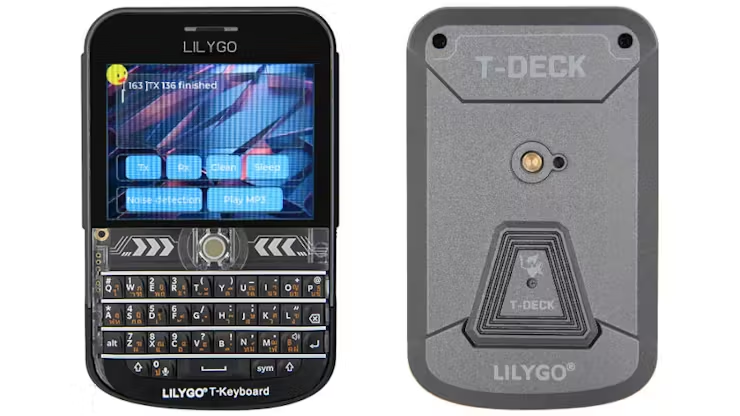
The LILYGO T-Deck is a compact, powerful handheld development device based on the ESP32-S3 microcontroller. It features a 2.8-inch touchscreen, keyboard, trackball, microphone, speaker, and optional LoRa/GPS support, making it ideal for portable embedded systems, IoT applications, and even cybersecurity projects.
In this post, we’ll explore:
- What the ESP32 microcontroller is.
- The ESP32-S3 architecture and why it’s powerful.
- How to set up Arduino IDE for development
- How to set up ESP-IDF for development
- Writing and flashing your first ESP-IDF program to print output to the serial monitor.
- Troubleshooting common setup issues.
What is the ESP32?
The ESP32 is a family of low-cost, low-power system-on-chip (SoC) microcontrollers developed by Espressif Systems. It is widely used for IoT, wireless communication, embedded systems, and AI applications due to its feature-rich architecture.
Some of the key features from the ESP32 are:
- Dual-core Xtensa LX6 (ESP32) or RISC-V (ESP32-C3/S3) processors.
- Wi-Fi 802.11 b/g/n and Bluetooth 4.2/5.0 support.
- Ultra-low power consumption with deep sleep modes.
- Rich peripherals: SPI, I2C, I2S, UART, ADC, DAC, PWM, and capacitive touch.
- On-chip SRAM and external PSRAM support.
- Real-time processing with FreeRTOS.
This alone is an awesome platform to put your development projects together.
ESP32-S3
The ESP32-S3 features a dual-core 32-bit Xtensa LX7 CPU with AI acceleration support and integrated USB, making it ideal for IoT, edge computing, and AI-powered applications.
Development Environment
We need a way to be able to develop software for this chip, so we have some things to install.
You can use a lot of different tools in order to write your software. Each have their own plugins that you can use to get the code flashed onto hardware. I use the Arduino IDE as it’s just simple to use.
Arduino IDE
The quickest way to get started is to follow the steps on the Xinyuan-LilyGO / T-Deck instructions up on GitHub. I’ve summarised those steps here for reference.
First up, get Arduino IDE installed.
Once you’ve got Arduino IDE running, open up “Preferences” to the “Settings” tab. We need to add an additional board manager URL
for the ESP32 series of boards: https://raw.githubusercontent.com/espressif/arduino-esp32/gh-pages/package_esp32_index.json. I had
quite a few issues running code that included TFT_eSPI unless I ran version 2.0.14 of these boards.
After this step you should be able to select ESP32S3 Dev Module as your board. This is what we’ll be deploying to.
From the Xinyuan-LilyGO / T-Deck repository, take all of the libraries under the
lib folder and copy them into your Arduino libraries folder. You should end up with something similar to this in your
Arduino folder:
└── libraries
    ├── AceButton
    ├── Arduino_GFX
    ├── es7210
    ├── ESP32-audioI2S
    ├── lvgl
    ├── RadioLib
    ├── SensorsLib
    ├── TFT_eSPI
    ├── TinyGPSPlus
    └── TouchLib
To finish the configuration, the “Tools” menu should have the following settings:
| Setting | Value |
|---|---|
| Board | ESP32S3 Dev Module |
| USB CDC On Boot | Enabled |
| CPU Frequency | 240 MHz (WiFi) |
| Core Debug Level | None |
| USB DFU On Boot | Disabled |
| Erase All Flash Before Sketch Upload | Disabled |
| Events Run On | Core 1 |
| Flash Mode | QIO 80MHz |
| Flash Size | 16MB (128Mb) |
| JTAG Adapter | Disabled |
| Arduino Runs On | Core 1 |
| USB Firmware MSC On Boot | Disabled |
| Partition Scheme | 16M Flash (3MB APP/9.9MB FATFS) |
| PSRAM | OPI PSRAM |
| Upload Mode | UART0 / Hardware CDC |
| Upload Speed | 921600 |
| USB Mode | Hardware CDC and JTAG |
We should be ready to go now.
First Program
Let’s write some super simple code, just to prove that we’re able to flash this device with the software that we’re writing.
void setup()
{
  Serial.begin(115200);

  delay(1000);
  Serial.println("T-DECK: Setup");
}

void loop()
{
  Serial.println("T-DECK: Loop");
  delay(1000);
}
The functions setup and loop should be very familiar to anyone who has written Arduino code.
The setup function is executed once, at the start. It’s normally used to set the board up. The loop function is executed
repeatedly from there, until the board is turned off.
To setup, we use Serial.begin to
set the rate of data for serial transmission. A delay is used to let the board settle, and then we write our first message out.
Our loop simply writes the T-DECK: Loop string once every second.
You should see something like this in your serial monitor:
T-DECK: Setup
T-DECK: Loop
T-DECK: Loop
T-DECK: Loop
T-DECK: Loop
Arduino-ESP32 is ideal for newcomers and hobby project as it’s quite simple to get running and just generally has a lower barrier to entry. You can get basic applications achieved quickly.
ESP-IDF
To unlock more power of your board, ESP-IDF (the Espressif IoT Development Framework) is
available. ESP-IDF allows you to break out of the setup() and loop() structures and allows you to write task-based applications.
You’ll get some better debugging and error handling, it is FreeRTOS-based, and you’ll also get immediate updates and bug fixes.
The process to get up and running can vary depending on the chip that you’re developing for. Espressif have pretty good documentation on their site with the Getting Started guide being available for all of their chip sets.
ESP32S3 which is what I’m using is really easy to get started with.
Dependencies
First are some operating system dependencies. As above, I’m on Arch Linux so the following dependencies are what I needed:
sudo pacman -S --needed gcc git make flex bison gperf python cmake ninja ccache dfu-util libusbESP-IDF
The installation of ESP-IDF is quite simple. It’s just grabbing their github repository at a given version into a well known directory on your machine:
cd ~
git clone -b v5.2.5 --recursive https://github.com/espressif/esp-idf.git
Tools
You can now use install.sh bundled with the github repository to install any extra tooling required for your board.
cd ~/esp-idf
./install.sh esp32s3
Integration
Finally, you’re going to need a way to drop into the ESP-IDF environment whenever you want. You can always just remember
to do this anytime you want to do any development; but I prefer to make an alias in my ~/.zshrc file.
alias get_idf='source $HOME/esp-idf/export.sh'Now, anytime I want to drop into that environment; I simply issue get_idf at the shell.
Ready
You’re just about ready to start development. So, let’s start a new project.
Get a copy of the hello_world example from the ~/esp-idf/examples/get-started folder, and put it into your source folder
somewhere (where ever you normally work from):
cp -r ~/esp-idf/examples/get-started/hello_world ~/src/tmp/hw

cd ~/src/tmp/hw
Code
Let’s take a quick look at the hello world example code:
void app_main(void)
{
    printf("Hello world!\n");

    /* Print chip information */
    esp_chip_info_t chip_info;
    uint32_t flash_size;
    esp_chip_info(&chip_info);
    printf("This is %s chip with %d CPU core(s), %s%s%s%s, ",
           CONFIG_IDF_TARGET,
           chip_info.cores,
           (chip_info.features & CHIP_FEATURE_WIFI_BGN) ? "WiFi/" : "",
           (chip_info.features & CHIP_FEATURE_BT) ? "BT" : "",
           (chip_info.features & CHIP_FEATURE_BLE) ? "BLE" : "",
           (chip_info.features & CHIP_FEATURE_IEEE802154) ? ", 802.15.4 (Zigbee/Thread)" : "");

    unsigned major_rev = chip_info.revision / 100;
    unsigned minor_rev = chip_info.revision % 100;
    printf("silicon revision v%d.%d, ", major_rev, minor_rev);
    if(esp_flash_get_size(NULL, &flash_size) != ESP_OK) {
        printf("Get flash size failed");
        return;
    }

    printf("%" PRIu32 "MB %s flash\n", flash_size / (uint32_t)(1024 * 1024),
           (chip_info.features & CHIP_FEATURE_EMB_FLASH) ? "embedded" : "external");

    printf("Minimum free heap size: %" PRIu32 " bytes\n", esp_get_minimum_free_heap_size());

    for (int i = 10; i >= 0; i--) {
        printf("Restarting in %d seconds...\n", i);
        vTaskDelay(1000 / portTICK_PERIOD_MS);
    }
    printf("Restarting now.\n");
    fflush(stdout);
    esp_restart();
}- We’re printing
"Hello world!" - We gather and print some chipset information
- We gather and print some memory information
- We countdown from 10, and restart
This program will continue in a loop, restarting the device.
Running
Connect your device to the machine now. When I connect mine, it uses /dev/tty:
ls /dev/tty*

/dev/ttyACM0
You’ll need to find yours on your machine, as you’ll use this reference to flash software onto.
Configure
idf.py set-target esp32s3
idf.py menuconfig
The set-target step will setup the necessary configurations for that specific board type. The menuconfig step will allow
you to customise any of those configs. I’ve always been fine to leave those configs, save and quit menuconfig.
Build
Now we can build.
idf.py buildAfter a bit of console scrolling, you should be left with some completion notes:
Executing action: all (aliases: build)
Running make in directory /home/michael/src/tmp/hw/build
Executing "make -j 10 all"...
[  0%] Built target memory.ld
[  0%] Built target sections.ld.in

. . .
. . . lots of text here
. . .

[100%] Built target hello_world.elf
[100%] Built target gen_project_binary
hello_world.bin binary size 0x2bd40 bytes. Smallest app partition is 0x100000 bytes. 0xd42c0 bytes (83%) free.
[100%] Built target app_check_size
[100%] Built target app

Project build complete. To flash, run:
idf.py flash
or
idf.py -p PORT flash
or
python -m esptool --chip esp32s3 -b 460800 --before default_reset --after hard_reset write_flash --flash_mode dio --flash_size 2MB --flash_freq 80m 0x0 build/bootloader/bootloader.bin 0x8000 build/partition_table/partition-table.bin 0x10000 build/hello_world.bin
or from the "/home/michael/src/tmp/hw/build" directory
python -m esptool --chip esp32s3 -b 460800 --before default_reset --after hard_reset write_flash "@flash_args"
Now we can flash this onto our device.
idf.py -p /dev/ttyACM0 flashYour device should now be running your software.
You can confirm this (for this particular program) by monitoring the serial output:
idf.py -p /dev/ttyACM0 monitorYou should see some output like this:
This is esp32s3 chip with 2 CPU core(s), WiFi/BLE, silicon revision v0.2, 2MB external flash
Minimum free heap size: 393180 bytes
Restarting in 10 seconds...
Restarting in 9 seconds...
Restarting in 8 seconds...
Restarting in 7 seconds...
Restarting in 6 seconds...
Restarting in 5 seconds...
Restarting in 4 seconds...
Restarting in 3 seconds...
Restarting in 2 seconds...
Restarting in 1 seconds...
Restarting in 0 seconds...
Restarting now.
ESP-ROM:esp32s3-20210327
Build:Mar 27 2021

. . .
. . . lots of text here
. . .
As we saw when we looked through the code, this is exactly what was expected.
Conclusion
We’ve explored two different ways to set up and develop software for ESP32-based chips: Arduino-ESP32 for quick prototyping and ESP-IDF for professional-grade development. The LILYGO T-Deck, with its touchscreen, keyboard, and connectivity options, makes an excellent platform for embedded applications, whether you’re experimenting with IoT, cybersecurity tools, or custom handheld devices.
If you’re new to embedded development, starting with Arduino-ESP32 is a great way to get familiar with the hardware. But to unlock the full power of the ESP32-S3, including multi-threading, advanced debugging, and FreeRTOS integration, consider diving deeper into ESP-IDF.
I hope to use the information in this article as a base platform for writing more posts in the future.