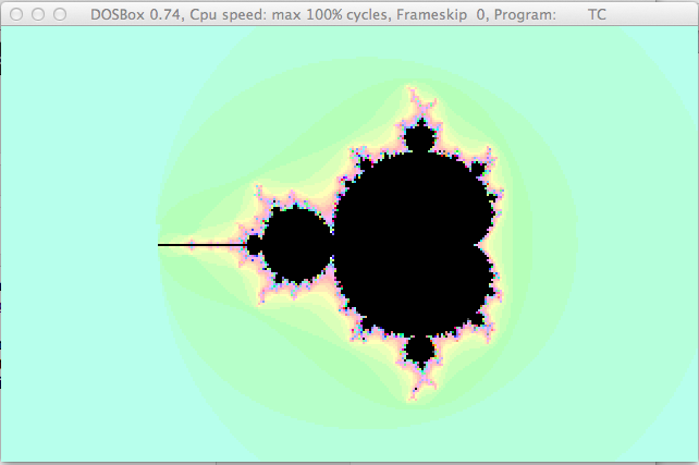
Another cool routine built off of some relatively simple mathematics is the mandelbrot set. Wikipedia has a really good write up if you’re a little rusty on the ins and outs of a mandelbrot set.
This tutorial assumes that you’ve already got a video display ready with a pointer to your buffer. We’ll just focus on the function that makes the doughnuts. Here’s the code, explanation to follow. This code has been lifted out of a file that I had in an old dos program. It was written using turbo C, but will port over to anything pretty easily.
Anyway, on to the code!
voidmandelbrot_frame(doublezoom,intmax_iter,intxofs,intyofs){doublezx=0,zy=0,cx=0,cy=0;/* enumerate all of the rows */for(inty=0;y<200;y++){/* enumerate all of the columns */for(intx=0;x<320;x++){/* initialize step variables */zx=zy=0;cx=(x-xofs)/zoom;cy=(y-yofs)/zoom;intiter=max_iter;/* calculate the iterations at this particular point */while(zx*zx+zy*zy<4&&iter>0){doubletmp=zx*zx-zy*zy+cx;zy=2.0*zx*zy+cy;zx=tmp;iter--;}/* plot the applicable pixel */video[x+(y*320)]=(unsignedchar)iter&0xff;}}}
So, you can see this code is very simple - to the point. We need to investigate all of the pixels (in this case 320x200 - or 64,000) and we calculate the iteration intersection at each point. The variables passed into the function allows the caller to animate the mandelbrot. zoom will take you further into the pattern, xofs and yofs will translate your position by this (x,y) pair. max_iter just determines how many cycles the caller wants to spend working out the iteration count. A higher number means that the plot comes out more detailed, but it slower to generate.
Whilst OpenGL enjoys a lot of fame as a 3D graphics package, it’s also a fully featured 2D graphics library as well. In this short tutorial, I’ll walk you through the code required to put OpenGL into 2D mode. This tutorial does assume that you’re ready to run some OpenGL code. It won’t be a primer in how to use SDL or GLUT, etc. Here’s the code.
/* first of all, we need to read the dimensions of the
display viewport. */intviewport[4];glGetIntegerv(GL_VIEWPORT,viewport);/* setup an orthographic matrix using the viewport
dimensions on the projection matrix */glMatrixMode(GL_PROJECTION);glLoadIdentity();glOrtho(0,viewport[2],viewport[3],0,-1,1);/* clear out the modelview matrix */glMatrixMode(GL_MODELVIEW);glLoadIdentity();/* disable depth testing (as we're not using z) */glDisable(GL_DEPTH_TEST);
First off, we use glGetIntegerv to read the dimensions of the viewport. You will probably already have these values on hand anyway, but getting the viewport this way just generalises the code and it’s not expensive to do so. We generate an orthographic matrix next using glOrtho and the viewport information we retrieved in the first step. The model view matrix is then kept clean - out of habbit, i’d say and finally `glDisable is used to turn off depth testing.
We’re in 2D. No Z-Axis, no depth testing! That’s it! You can draw what you need to as simply as this:
/* note that we're not clearing the depth buffer */glClear(GL_COLOR_BUFFER_BIT);glMatrixMode(GL_MODELVIEW);glLoadIdentity();/* draw a triangle */glBegin(GL_TRIANGLES);glColor3ub(255,0,0);glVertex2d(0,0);glColor3ub(0,255,0);glVertex2d(100,0);glColor3ub(0,0,255);glVertex2d(50,50);glEnd();
Quick update to this one - I switched the parameters around in the call to glOrtho so that it’s a much more natural drawing experience (putting 0,0 in the top left hand corner of the screen). It’s not perfect mathematically but it sure does help any of your existing code that assumes your screen goes positive to the right and positive to the bottom!
Kicking back into old, old, old school mode, I had found another cool effect laying around that seemed to work really well in dosbox. It’s a plasma (if you couldn’t tell from the title). Plasmas are the cool, blobby sort of shapeless eye-grabbers that are seriously cool and simple. The basic mathematical thory of the plasma is simple.
4 state counters for the program track where you’re up to overall
4 state counters per frame render track where you’re up to for that frame
Each pixel is the result of these 4 cosine wave intersections. You can include the x and y counting dimensions to add the 6 intersections.
That’s it really. There’s a little special sauce to make the plasma move and mutate but they really have no bearing over the generation of the effect itself.
Cosine? Easy, I’ll just call cosf()!
Well, not quite. This is a demo routine that will entirely written in assembly language (8086 assembly language to be exact) and as such we won’t have the luxury of a math library (or math-coprocessor) to do the work of finding out cosine values. So, we must pre-calculate. A small C application gives us all the table pre-calculation we’ll need for this application. It’s good to keep this application handy to re-pre-calculate this table to taste. If you like a little extra calculation to go into your cos table, that is. Me, I like nerdy numbers. So, according to this cos table, there are 256 degress in a circle (see what I did there) and the top of the cos curve (1.0) is 255 moving through the centre point (0.0) at 127 all the way down to the bottom point (-1.0) at 0.
Here’s the code to generate that table.
#include<stdio.h>
#include<math.h>#define PI_BY_2 (3.14159f * 2)
intmain(intargc,char*argv[]){inttheta=0,count=0,count2=0;unsignedcharvalues[256];for(theta=0;theta<=255;theta++){floatangle=((float)theta/256.0f)*PI_BY_2;values[theta]=(unsignedchar)((cosf(angle)*127.0f)+127.0f);}printf("costab DB ");for(count=0;count<32;count++){for(count2=0;count2<8;count2++){printf("%03xh, ",values[(count<<3)+count2]);}printf("\n DB ");}return0;}
Here is the table that is generated when running this code.
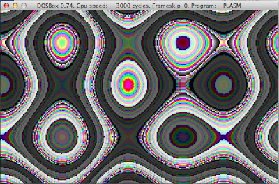
Ooooh aaahhh, that’s a nerdy cosine table! Now that we’ve solved all of the world’s mathematical problems here, it’s on to the effect! Just getting 4 counters to run over this cosine table and intersect with each other can produce a mesmerising result. Without setting a palette (the standard vga palette is a bit: ewwwwww), here’s how the effect looks:
Feel like you’re at Woodstock yet? So, the effect really spans across two smaller functions, which I’ve tried to comment as best I can below. Here’s drawing a single frame:
plasma_frame:; jump over the local variablesjmpplasma_frame_codetemp_phase_1DB0temp_phase_2DB0temp_phase_3DB0temp_phase_4DB0y_locDW0plasma_frame_code:; setup where we'll draw toxordi,di; setup a pointer to our cos tableleasi,costab; iterate over every pixelmovcx,64000; setup temp state into 3 and 4moval,phase_3movtemp_phase_3,almoval,phase_4movtemp_phase_4,alreset_1_and_2:; re-setup temp state into 1 and 2moval,phase_1movtemp_phase_1,almoval,phase_2movtemp_phase_2,al; save our overall progresspushcx; process the next row of pixelsmovcx,320plasma_frame_pixel:; calculate the pixel value; col = costab[t1] + costab[t2] + costab[t3] + costab[t4] xorbx,bxmovbl,temp_phase_1moval,ds:[si+bx]movbl,temp_phase_2addal,ds:[si+bx]adcah,0movbl,temp_phase_3addal,ds:[si+bx]adcah,0movbl,temp_phase_4addal,ds:[si+bx]adcah,0; draw the pixelmoves:[di],al; adjust counter 1moval,temp_phase_1addal,2movtemp_phase_1,al; adjust counter 2moval,temp_phase_2subal,1movtemp_phase_2,al; move onto the next pixelincdideccxjnzplasma_frame_pixel; adjust the y location by 1incy_locpopcx; adjust counter 3moval,temp_phase_3addal,2movtemp_phase_3,al; adjust counter 4moval,temp_phase_4subal,1movtemp_phase_4,alsubcx,320jnzreset_1_and_2ret
Drawing a single frame isn’t too difficult at all. It’s important to remember that es:[di] is pointing to the vga buffer to draw to where as ds:[si] is pointing at the cosine table. We’re using bx as a base pointer to offset si such that it acts as our array index. Neat-O!
Between frame draws, we need to make the plasma MOVE!!.. This is just some simple additions or subtractions. Using random values adds a sense of entropy to the process making the plasma move in an almost unpredictable way. It’s a little more organic this way. I haven’t done it this way though. The code you’ll see below moves the plasma by fixed amounts per frame. Still gives it some movement.
Wrapping those two calls in a loop that waits for a key to be pressed is all you should need to draw a plasma to the screen.
Things for you to do:
Change the cosine table generation to produce a more interesting cosine curve
Apply a palette to take the 60’s-ness out of the default palette
Apply a palette that you can cycle through (like 1024 or 2048 entries in size) so that the palette (and therefore the plasma) will morph colour as frames progress
Here’s a little tid-bit that I’d like to make note of. In a previous MASM32 windows development tutorial, I needed a random number generator and was able to dig this one up from the archives.
First of all, you need to make sure we’re using the 586 instruction set - at least!
; minimum instruction set requirement.586
Shortly, it will become clear why we need the 586 instruction set. To support the random number generator, we need a bit of state in the shape of two double-words.
; calculation stateprng_xDD0; current seedprng_aDD100711433
These two variables allow the random number generator to know where it’s up to for the next iteration. Changing the initial seed of course will change the sequence of random values that are produced by this routine. The actual function that produces the random number look like this:
PrngGetPROCrange:DWORD; count the number of cycles since; the machine has been resetrdtsc; accumulate the value in eax and manage; any carry-spill into the x state varadceax,edxadceax,prng_x; multiply this calculation by the seedmulprng_a; manage the spill into the x state varadceax,edxmovprng_x,eax; put the calculation in range of what; was requestedmulrange; ranged-random value in eaxmoveax,edxretPrngGetENDP
There it is. That first instruction RDTSC is what we need to turn the 586 instruction set on for. This mnemonic stands for Read Time-Stamp Counter. It will take the number of cycles since the machine has been reset and put this count into the EDX:EAX pair (as the time stamp counter is a 64bit value). From there some calculations are performed to ensure the consistency of state between random value retrieves and also capping to the requested range.