Getting Started with the RP2350
22 Jul 2025Introduction
Raspberry Pi has a reputation for delivering accessible and powerful hardware for makers and professionals alike—from credit card–sized Linux computers to the remarkably capable RP2040 microcontroller.
Now they’ve introduced something new: the RP2350, a dual-core microcontroller with a twist. Not only does it offer more memory, more peripherals, and improved performance, but it can also boot into either an Arm Cortex-M33 or a RISC-V Hazard3 core.
In this post, we’ll take a tour of the RP2350’s features, look at why this chip is a step forward for embedded development, and then walk through a hands-on example using the Embassy framework in Rust. If all goes well, we’ll end up with a blinking LED—and a better sense of what this chip can do.
All of the code for this article can be found up on GitHub.
RP2350
Raspberry Pi’s RP2040 quickly became a favorite among hobbyists and professionals alike, with its dual-core Cortex-M0+, flexible PIO system, and excellent documentation. Now, the RP2350 ups the ante.
Announced in mid-2025, the RP2350 is Raspberry Pi’s next-generation microcontroller. While it shares the foundational philosophy of the RP2040—dual cores, PIO support, extensive GPIO—it introduces a radical new idea: you can boot it into either Arm Cortex-M33 mode or Hazard3 RISC-V mode.
This dual-architecture design means developers can choose the ISA that best suits their toolchains, workflows, or community contributions. It’s a versatile chip for an increasingly diverse embedded world.
Dual Architectures: Cortex-M33 vs Hazard3 RISC-V
The RP2350 includes two processor cores that can each boot into either:
- Arm Cortex-M33: A powerful step up from the RP2040’s M0+ cores, the M33 includes:
- Hardware FPU and DSP instructions.
- TrustZone-M for secure code partitioning.
- Better interrupt handling and performance at 150 MHz.
- Hazard3 RISC-V: A custom-designed RV32IMAC core written in Verilog, Hazard3 offers:
- Open-source hardware transparency.
- A lean, high-efficiency implementation suited for embedded work.
- Toolchain portability for RISC-V developers and researchers.
Each RP2350 can only run one architecture at a time—selectable via boot configuration—but this choice opens up new tooling ecosystems and development styles.
Feature Highlights
The architectural flexibility is backed by strong hardware specs:
- Clock speed: Up to 150 MHz.
- SRAM: 520 KB split across 10 banks, providing more headroom than the RP2040’s 264 KB.
- Flash: Optional in-package 2 MB QSPI flash (RP2354 variants).
- PIO: 3 PIO blocks (12 state machines total) for advanced I/O handling.
- Peripherals: USB 1.1 host/device, 8 ADC channels, 24 PWM channels, 6 UARTs, 4 SPI, 4 I²C.
- Security: TrustZone, SHA-256 engine, true RNG, glitch hardening, OTP-signed boot.
- Packages: Available in QFN-56 and QFN-48 variants with 30–48 GPIOs.
In short, the RP2350 is built not only for flexibility but also for serious embedded applications.
Gotchas and GPIO Leakage (Errata E9)
Like all first-generation silicon, the RP2350 has some quirks. The most notable is Errata RP2350-E9, which affects GPIO Bank 0:
When configured as inputs, these GPIOs can latch in a mid-state (~2.2V) and leak current (~120 µA). This persists even when the core is in sleep mode.
The workaround is simple: explicitly configure unused or input pins as outputs or with defined pull states. For blinking an LED on an output pin, you’re in the clear—but this is worth noting for more complex setups.
Development
The main purpose of working with these boards is to put some functionality on there that’s your custom application. Rust support for the RP2350 is surprisingly solid, giving us access to a memory-safe, modern systems language—something traditionally missing from embedded environments dominated by C and assembly.
Let’s dive in and get your local development environment setup.
Environment Setup
Before we start writing code, we need to make sure the development environment is ready. This includes updating Rust, installing the correct cross-compilation target, and installing some board-specific tools.
First, ensure your Rust toolchain is up to date:
rustup updateThis guarantees you’ll have the latest stable compiler, tooling, and support for embedded targets.
thumbv8m.main-none-eabihf
The RP2350 uses Arm Cortex-M33 cores, which are part of the Armv8-M Mainline architecture. To compile code for this platform, we need the corresponding Rust target:
rustup target add thumbv8m.main-none-eabihfLet’s break that down:
thumb: We’re targeting the 16-bit Thumb instruction set used in embedded ARM.v8m.main: This is the Armv8-M Mainline profile, used by Cortex-M33 (not to be confused withbaseline, used by M0/M0+).none: There’s no OS—we’re writing bare-metal firmware.eabihf: We’re linking against the Embedded Application Binary Interface with hardware floating point support, which the M33 core provides.
picotool
The RP2350 supports USB boot mode, where it presents itself as a mass storage device for drag-and-drop firmware
flashing. Raspberry Pi provides a CLI tool called picotool for inspecting and interacting with the board:
yay -S picotool-gitIf you’re on a Debian-based distro:
sudo apt install cmake gcc-arm-none-eabi libusb-1.0-0-dev
git clone https://github.com/raspberrypi/picotool.git
cd picotool
mkdir build && cd build
cmake ..
make
sudo make install
picotool allows you to:
- Read info from the chip (e.g. flash size, name, build ID).
- Reboot into BOOTSEL mode programmatically.
- Flash
.uf2or.binfiles from the CLI.
It’s optional for simple workflows (drag-and-drop still works), but helpful for automation and diagnostics. We’ll use it as a build step so that we can automate the deployment of our firmware as a part of our build chain.
Project Setup
Let’s create our project. If you’re using the command line, the standard way to start a new Rust binary crate is:
cargo new blink --bin
cd blink
This gives us a fresh directory with a Cargo.toml file and a src/main.rs entry point. We’ll modify these files as
we go to configure them for embedded development on the RP2350.
If you’re using an IDE like RustRover, you can create a new binary project through its GUI instead—just make sure you select the correct directory structure and crate type.
Dependencies
Now let’s configure the project’s dependencies in Cargo.toml. For this project, we’re using the async Embassy
framework, along with some standard crates for ARM Cortex-M development and debug output.
Here’s the [dependencies] section we’re using:
[package]
name = "rp2350_blink"
version = "0.1.0"
edition = "2024"

[dependencies]
defmt-rtt = "0.4"
panic-probe = { version = "0.3" }

cortex-m = { version = "0.7.6" }
cortex-m-rt = "0.7.0"

embassy-executor = { git = "https://github.com/embassy-rs/embassy", rev = "dc18ee2", features = [
    "arch-cortex-m",
    "executor-thread",
    "defmt",
    "integrated-timers",
] }
embassy-time = { git = "https://github.com/embassy-rs/embassy", rev = "dc18ee2" }
embassy-rp = { git = "https://github.com/embassy-rs/embassy", rev = "dc18ee2", features = [
    "defmt",
    "time-driver",
    "critical-section-impl",
    "rp235xa",
    "binary-info",
] }
Let’s break that down:
defmt-rtt: Enables efficient logging over RTT (Real-Time Transfer) with support fromprobe-rs.panic-probe: A minimal panic handler that emits debug output viadefmt.cortex-mandcortex-m-rt: Core crates for bare-metal development on ARM Cortex-M processors.embassy-executor: Provides the async task executor and interrupt management.embassy-time: Gives us an async timer API—used to await delays, intervals, and timeouts.embassy-rp: The HAL (hardware abstraction layer) for Raspberry Pi microcontrollers, including the RP2040 and now the RP2350.
Note the use of the Git repository and revision pinning for Embassy. As of this writing, the RP2350 support is still very fresh, so we’re tracking a specific commit directly.
We’ve also enabled several features in embassy-rp:
"rp235xa"enables HAL support for the RP2350A/B variants."binary-info"enables metadata output used by tools likeelf2uf2-rsandpicotool.
This sets up our project with a modern, async-capable embedded toolchain.
Embassy
For this project, I chose the Embassy framework to build the firmware in Rust. Embassy is an async-first embedded framework that offers:
- Cooperative async tasks using
async/await. - Efficient memory usage via static allocation and task combinators.
- A clean HAL abstraction layer that works with the RP family via
embassy-rp.
Embassy’s async executor avoids blocking loops and instead models hardware events and delays as tasks. This is ideal for power-sensitive or multitasking applications, and it maps well to the RP2350’s interrupt-driven design.
Of course, async requires careful setup—especially for clocks, peripherals, and memory—but Embassy makes this manageable. For a simple blink, it’s an elegant demo of Rust’s expressive power on embedded systems.
Memory Layout
Embedded development means you’re in charge of exactly where your program lives in memory. Unlike typical desktop environments, there’s no OS or dynamic linker—your firmware needs to specify where code, data, and peripherals live, and how the linker should lay it all out.
In our case, the RP2350 gives us a mix of Flash, striped RAM, and dedicated SRAM banks. To make this work,
we define a memory layout using a memory.x file (or inline in a .ld linker script), which tells the linker where to
place things like the .text, .data, and .bss sections.
Here’s what that looks like for the RP2350:
MEMORY {
    FLASH : ORIGIN = 0x10000000, LENGTH = 2048K
    RAM : ORIGIN = 0x20000000, LENGTH = 512K
    SRAM4 : ORIGIN = 0x20080000, LENGTH = 4K
    SRAM5 : ORIGIN = 0x20081000, LENGTH = 4K
}
We define FLASH as having 2mb memory starting at 0x10000000.
RAM is made up of 8 banks SRAM0, SRAM1 . . . SRAM7, with a striped mapping.
The final two ram banks are defined as a direct mapping. This can be useful for dedicated tasks.
The rest of the linker script defines how specific sections are placed and aligned:
SECTIONS {
    .start_block : ALIGN(4)
    {
        __start_block_addr = .;
        KEEP(*(.start_block));
        KEEP(*(.boot_info));
    } > FLASH
} INSERT AFTER .vector_table;

_stext = ADDR(.start_block) + SIZEOF(.start_block);
.start_block and .boot_info go at the beginning of flash, where the RP2350’s boot ROM and picotool expect to find
them.
SECTIONS {
    .bi_entries : ALIGN(4)
    {
        __bi_entries_start = .;
        KEEP(*(.bi_entries));
        . = ALIGN(4);
        __bi_entries_end = .;
    } > FLASH
} INSERT AFTER .text;
.bi_entries contains metadata used by picotool for introspection.
SECTIONS {
    .end_block : ALIGN(4)
    {
        __end_block_addr = .;
        KEEP(*(.end_block));
    } > FLASH
} INSERT AFTER .uninit;

PROVIDE(start_to_end = __end_block_addr - __start_block_addr);
PROVIDE(end_to_start = __start_block_addr - __end_block_addr);
.end_block can hold signatures or other trailing metadata after the main firmware.
This layout ensures compatibility with the RP2350’s boot process, keeps your binary tool-friendly, and gives you fine-grained control over how memory is used.
If you’re using Embassy and Rust, you’ll usually reference this layout in your memory.x file or directly via your
build system (we’ll get to that next).
Build System
With our target and memory layout configured, we now set up the build system to compile and flash firmware to the
RP2350 using picotool.
Cargo Configuration
In .cargo/config.toml, we define the architecture target and a custom runner:
[target.'cfg(all(target_arch = "arm", target_os = "none"))']
runner = "sudo picotool load -u -v -x -t elf"

[build]
target = "thumbv8m.main-none-eabihf"

[env]
DEFMT_LOG = "debug"
Let’s unpack that:
- The
[target.'cfg(...)']section sets a custom runner for all ARM, bare-metal targets. In this case, we usepicotoolto flash the.elffile directly to the RP2350. - The
-uflag unmounts the device after flashing. - The
-vand-xflags enable verbose output and reset the device after load. - The
-t elfspecifies that we’re loading the.elffile rather than converting to.uf2. [build] target = ...ensures Rust compiles for thethumbv8m.main-none-eabihfarchitecture.[env] DEFMT_LOG = "debug"sets the global defmt log level used in builds.
This setup is flexible and scriptable—you can cargo run --release and it will compile your firmware, then use
picotool to flash it directly to the board in BOOTSEL mode.
To use this setup, just run:
cargo run --releaseMake sure the RP2350 is in BOOTSEL mode when connected. We’ll cover deployment details in the next section.
Custom Build Script (build.rs)
To ensure our linker configuration works reliably across platforms and tooling, we include a small build script in
build.rs. This script:
- Copies
memory.xinto the output directory where the linker expects it. - Sets the linker search path (
rustc-link-search). - Adds linker arguments for
link.xanddefmt.x. - Tells Cargo to re-run the build if
memory.xchanges.
Here’s the full script:
use std::env;
use std::fs::File;
use std::io::Write;
use std::path::PathBuf;

fn main() {
    // Copy memory.x to OUT_DIR so the linker can find it
    let out = &PathBuf::from(env::var_os("OUT_DIR").unwrap());
    File::create(out.join("memory.x"))
        .unwrap()
        .write_all(include_bytes!("memory.x"))
        .unwrap();

    // Tell rustc to link using this path
    println!("cargo:rustc-link-search={}", out.display());

    // Rebuild if memory.x changes
    println!("cargo:rerun-if-changed=memory.x");

    // Pass linker flags for defmt and linker script
    println!("cargo:rustc-link-arg-bins=--nmagic");
    println!("cargo:rustc-link-arg-bins=-Tlink.x");
    println!("cargo:rustc-link-arg-bins=-Tdefmt.x");
}
This script ensures everything works smoothly whether you’re using cargo build, cargo run, or more advanced tools
like probe-rs. It’s an essential part of working with custom memory layouts in embedded Rust projects.
Main Code
With our project set up and build system configured, it’s time to write our main code.
#![no_std]
#![no_main]
We’re building a bare-metal binary—no operating system, no standard library. These attributes disable Rust’s usual runtime features like heap allocation and system startup, allowing us to define our own entry point and panic behavior.
#[unsafe(link_section = ".start_block")]
#[used]
pub static IMAGE_DEF: ImageDef = ImageDef::secure_exe();
This embeds the required image header into the beginning of flash—right where the RP2350’s boot ROM expects to find it.
We discussed this earlier in the memory layout section: .start_block must live in the first 4K of flash to be
recognized at boot time.
Embassy provides the ImageDef::secure_exe() helper to generate a valid, signed header.
#[unsafe(link_section = ".bi_entries")]
#[used]
pub static PICOTOOL_ENTRIES: [embassy_rp::binary_info::EntryAddr; 4] = [
    embassy_rp::binary_info::rp_program_name!(c"Blink"),
    embassy_rp::binary_info::rp_program_description!(
        c"The RP Pico Hello, World application blinking the led connected to gpio 25"
    ),
    embassy_rp::binary_info::rp_cargo_version!(),
    embassy_rp::binary_info::rp_program_build_attribute!(),
];
These entries provide metadata to picotool, which can read the program name, description, version, and build flags.
This is part of what makes the RP family easy to work with—it’s designed for introspection and tooling.
These entries live in the .bi_entries section of flash, as specified in our linker script.
#[embassy_executor::main]
async fn main(_spawner: Spawner) {
    . . .
}
Embassy uses an async runtime with a cooperative executor. The #[embassy_executor::main] macro sets up interrupt
handlers and boot logic. The executor runs tasks defined with async/await rather than traditional blocking loops.
In this example, we don’t spawn any extra tasks—we just use the main task to blink the LED.
let p = embassy_rp::init(Default::default());
let mut led = Output::new(p.PIN_25, Level::Low);
loop {
led.set_high();
Timer::after_millis(500).await;
led.set_low();
Timer::after_millis(500).await;
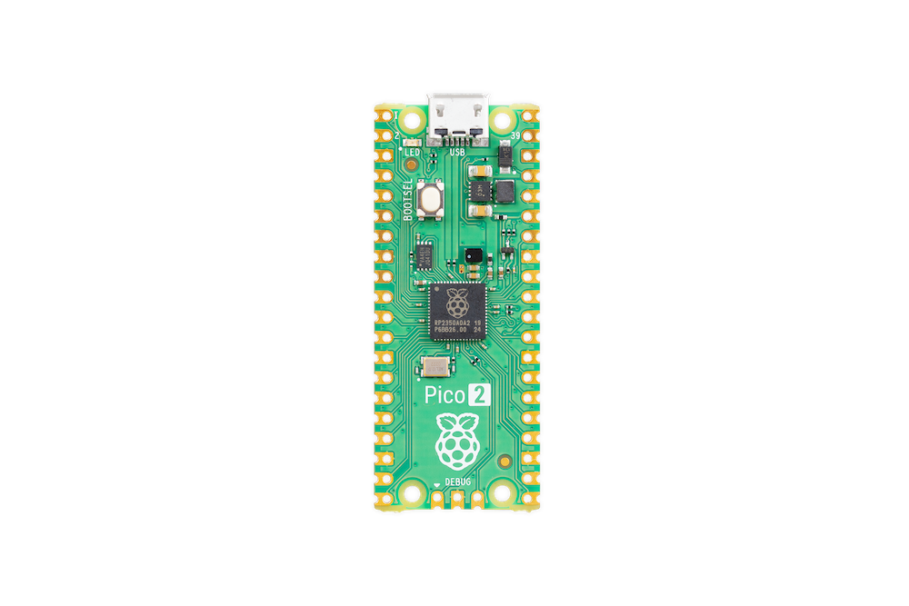
}The following diagram shows the pinout of the Pico 2.

At the top of the diagram, you can see that GP25 is connected to the LED, which is why we’re integrating with that pin.
embassy_rp::init()initializes peripherals.PIN_25is the onboard LED on most RP boards.- We toggle it on and off with
set_high()andset_low(), awaiting 500 ms between transitions.
Thanks to Embassy’s async timers, we don’t block the CPU—we yield control and resume when the delay expires. This model is more efficient than spinning in a tight loop or using busy-waits.
Together, these components demonstrate how a memory-safe, modern Rust framework can map cleanly onto a low-level microcontroller like the RP2350—while still giving us full control over boot, layout, and execution.
Deployment
With our firmware built and ready, it’s time to deploy it to the board.
BOOTSEL Mode
The RP2350 (like the RP2040 before it) includes a USB bootloader in ROM. When the chip is reset while holding down a designated BOOTSEL pin (typically attached to a button), it appears to your computer as a USB mass storage device.
To enter BOOTSEL mode:
- Hold down the BOOTSEL button.
- Plug the board into your computer via USB.
- Release the BOOTSEL button.
You should now see a new USB drive appear (e.g., RPI-RP2 or similar).
This is how the chip expects to be flashed—and it doesn’t require any special debugger or hardware.
Flashing with picotool
Instead of manually dragging and dropping .uf2 files, we can use picotool to flash the .elf binary directly from
the terminal.
Since we already set up our runner in .cargo/config.toml, flashing is as simple as:
cargo run --releaseUnder the hood, this runs:
sudo picotool load -u -v -x -t elf target/thumbv8m.main-none-eabihf/release/rp2350_blinkThis does several things:
- Uploads the
.elffile to the RP2350 over USB. - Unmounts the device (
-u), ensuring no filesystem issues. - Verifies the flash (
-v) and resets the board (-x).
After Flashing
Once the firmware is written:
- The RP2350 exits BOOTSEL mode.
- It reboots and starts executing your code from flash.
- If everything worked, your LED should now blink—congratulations!
You can now iterate quickly by editing your code and running:
cargo run --releaseJust remember: if the program crashes or you need to re-flash, you’ll have to manually put the board back into BOOTSEL mode again.
Conclusion
The RP2350 is a bold step forward in Raspberry Pi’s microcontroller line—combining increased performance, modern security features, and the unique flexibility of dual-architecture support. It’s early days, but the tooling is already solid, and frameworks like Embassy make it approachable even with cutting-edge hardware.
In this post, we set up a full async Rust development environment, explored the RP2350’s memory layout and boot expectations, and flashed a simple—but complete—LED blink program to the board.
If you’ve made it this far: well done! You’ve now got a solid foundation for exploring more advanced features—from PIO and USB to TrustZone and dual-core concurrency.